The cutting tip is the most consequential component in any oxy-fuel system. Regulators control pressure, hoses deliver gas, and the torch body provides the handle — but the tip determines whether the cut is clean or ragged, fast or sluggish, safe or prone to backfire. Getting the tip selection right and operating it correctly separates a consistent, productive cut from wasted gas and rework. This guide covers everything from tip design principles to practical field techniques and defect diagnosis.
Content
What Oxy Fuel Cutting Tips Actually Do
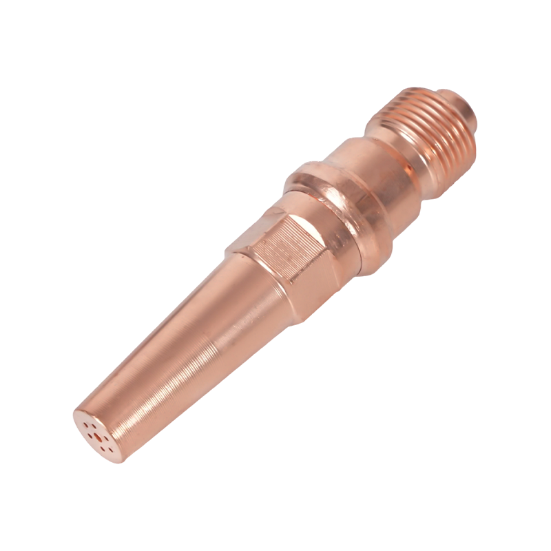
An oxy-fuel cutting tip has two distinct functions that happen simultaneously. The outer ring of small holes — the preheat orifices — deliver a mixture of fuel gas and oxygen to produce a preheating flame. This flame heats the base metal to its ignition temperature: roughly 1,600–1,800°F (870–980°C) for mild steel. The central bore serves an entirely different purpose: it delivers a high-pressure jet of pure cutting oxygen that chemically oxidizes the preheated steel and blows the resulting molten iron oxide (slag) out of the kerf.
This distinction matters practically. The preheat flame does not cut — it conditions the metal. The cutting oxygen stream does the actual severing through a chemical reaction, not brute thermal melting. Any factor that degrades the cutting oxygen stream — low pressure, contaminated bore, incorrect standoff distance — directly affects cut quality, regardless of how well the preheat flame looks.
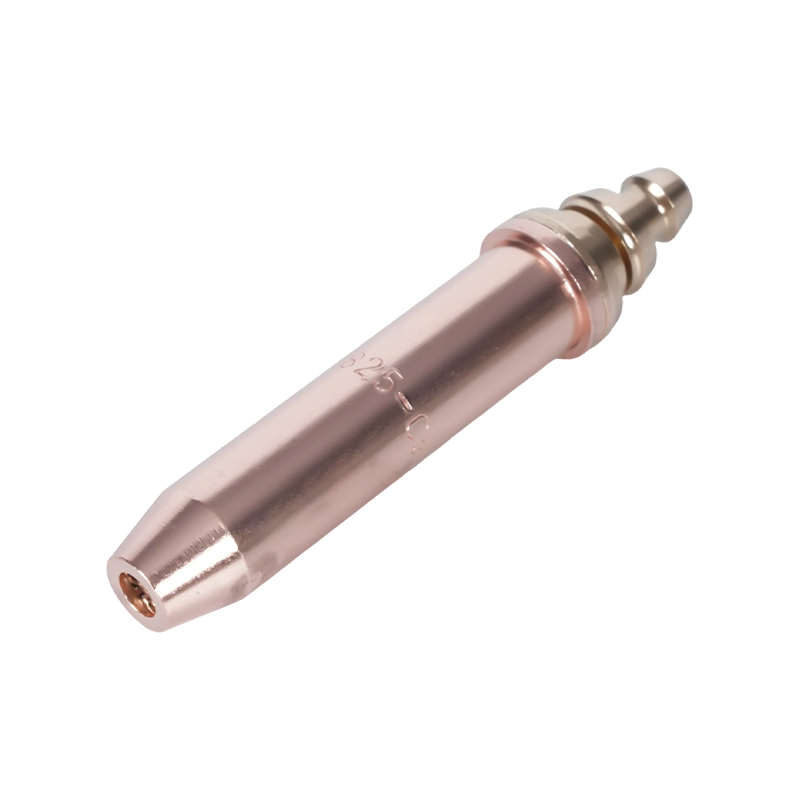
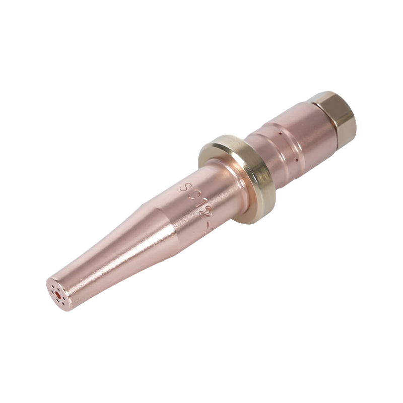
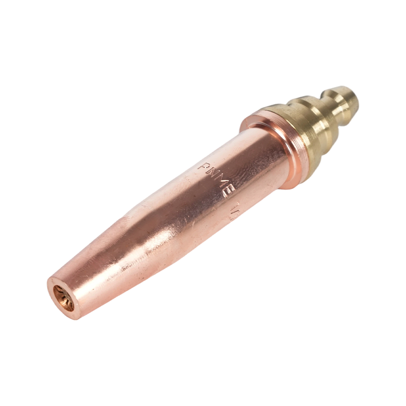
Tips are manufactured in one piece (solid copper) or two-piece designs (brass inner with copper outer). Two-piece tips are more common in production environments because the inner piece can be replaced independently when the preheat orifices wear, without discarding the outer body. One-piece tips are simpler and often preferred for hand cutting where replacement frequency is lower.
Choosing the Right Tip: Size, Bore Type, and Fuel Gas
Three variables govern tip selection: material thickness, cutting oxygen bore design, and the fuel gas in use. Selecting on thickness alone — without accounting for bore type and fuel compatibility — is the most common source of poor cut quality in the field.
Tip Size and Material Thickness
Tip size determines the diameter of the central cutting oxygen bore and the size of the preheat orifices. The correct tip size is always matched to material thickness, not to a preferred pressure setting or cutting speed. Using an oversized tip on thin plate causes excess heat input, warping, and wide, ragged kerfs. Using an undersized tip on thick plate produces incomplete oxidation, heavy slag adhesion, and an inability to complete the cut at depth.
| Material Thickness | Typical Tip Size | Oxygen Pressure (PSI) | Cutting Speed (IPM) |
|---|---|---|---|
| 1/8 in (3 mm) | 000 / 0 | 20–25 | 20–26 |
| 1/4 in (6 mm) | 0 / 1 | 25–35 | 16–22 |
| 1/2 in (13 mm) | 1 / 2 | 35–45 | 12–18 |
| 1 in (25 mm) | 2 / 3 | 40–55 | 10–14 |
| 2 in (50 mm) | 3 / 4 | 45–65 | 7–10 |
| 4 in (100 mm) | 4 / 5 | 55–80 | 4–7 |
Cylindrical Bore vs. Divergent Bore
Cutting oxygen bores come in two internal geometries, each optimized for a different thickness range. Cylindrical bore tips maintain a constant diameter through the full length of the bore and operate best at around 40 PSI. They are the standard choice for hand cutting and machine cutting of material up to 3/8 inch (10 mm) thick. Divergent bore tips flare outward toward the exit, allowing the cutting oxygen stream to expand to supersonic velocity. They operate at higher pressures — typically 75 to 100 PSI — and deliver faster cutting speeds with lower oxygen consumption per foot of cut on plate thicker than 3/8 inch. For most CNC oxy-fuel machines cutting heavy plate, divergent bore tips are the correct choice. For a detailed comparison of how fuel gas selection interacts with tip bore design and flame temperature, see our cutting torch temperatures and fuel gas comparison.
Fuel Gas Compatibility
Cutting tips are not interchangeable across fuel gases. Acetylene tips have a specific preheat orifice pattern and size that suit acetylene's concentrated inner-cone heat and its stoichiometric oxygen-to-fuel ratio of approximately 1:1. Propane and propylene tips have more and larger preheat orifices to compensate for these gases' lower inner-cone temperatures and their higher oxygen demand — propane requires roughly 4.5 parts oxygen per part fuel. Using an acetylene tip with propane starves the preheat flame and produces incomplete heating; using a propane tip with acetylene creates an excessively large, uncontrolled preheat flame. Always confirm that the tip is rated for the specific fuel gas being used.
Setting Up for a Clean Cut
Even a correctly sized tip produces poor results if pressure, flame, and standoff are not set properly before the cut begins.
Set pressure at the tip, not at the regulator. Long hose runs and narrow hose diameters create measurable pressure drop between the regulator outlet and the torch. For runs exceeding 25 feet, attach test gauges at the torch inlet to measure the actual delivery pressure, then adjust the regulator upward until the torch-side gauges read the values specified in the tip chart. Cutting from regulator pressure alone on a long run is a common cause of sluggish cuts and heavy slag. For a complete breakdown of gas selection and safe pressure management, refer to our oxy-fuel safety and gas selection guide.
Dial in a neutral flame before cutting. Light the torch on fuel only, then introduce preheat oxygen until the inner cone sharpens to a well-defined bright blue point surrounded by a clear outer envelope. This is the neutral flame — the correct starting point for virtually all steel cutting. An oxidizing flame (shorter, more pointed cone with a purplish tinge) prematurely oxidizes the metal surface and produces a heat-affected zone that resists clean cutting. A carburizing flame (soft, feathered cone with a secondary orange envelope) deposits carbon on the metal surface and also degrades cut quality.
Maintain consistent standoff distance. For most hand cutting tips, the correct standoff is 1/8 to 1/4 inch (3–6 mm) between the tip face and the workpiece surface. Too close and the tip overheats, the preheat orifices clog with spatter, and backfire risk increases. Too far and the cutting oxygen stream loses coherence before reaching the metal, producing a wide, rounded kerf and heavy dross.
Confirm the metal has reached ignition temperature before opening the cutting oxygen. The correct visual indicator is a bright cherry-red to orange-white glow at the pierce point. A useful field test: slightly depress the cutting oxygen lever — if the metal immediately begins to spark and oxidize, it is ready. If it simply cools and darkens, continue preheating.
8 Practical Tips for Better Cuts
The following techniques address the most common sources of inconsistent results in both hand and machine oxy-fuel cutting operations.
- Use the tip chart for your specific brand. Flow rates and orifice dimensions vary between manufacturers even for the same nominal tip size. A tip chart from one brand should never be applied to another brand's tips.
- Brace your cutting hand. For hand cutting, support the torch hand with the free hand resting on the workpiece or a stable reference surface. Torch wobble of even 1/16 inch produces visible waviness in the cut edge.
- Pierce with a tilt, then go perpendicular. When piercing mid-plate rather than starting from an edge, tilt the torch 15–20 degrees away from the direction of travel as you open the cutting oxygen. This directs the initial slag ejection away from the tip face. Once the pierce is complete, bring the torch back to perpendicular and begin the cut.
- Roll in at edges, roll out at the finish. When starting at the edge of thick plate, roll the torch from an angled position into perpendicular as you enter the cut. At the end of the cut, roll the torch outward to ensure the bottom of the kerf severs cleanly — without this, the final inch of a thick cut often remains partially connected.
- Match travel speed to the sparks. At the correct travel speed, the cutting oxygen stream exits from the bottom of the workpiece at a slight trailing angle (5–10 degrees behind the torch direction). If the stream exits vertically, the travel speed is too slow. If it exits with a pronounced forward lean, the speed is too fast and the cut is not fully penetrating.
- Keep the tip clean during operation. Spatter buildup on the tip face during long cuts progressively degrades the preheat flame shape and can cause the cutting oxygen stream to deflect. A brief pause to clean with a tip cleaner file restores performance without a full shutdown.
- Close fuel before oxygen on shutdown. When shutting down the torch, close the fuel valve first, then the cutting oxygen, then the preheat oxygen. This sequence prevents a fuel-rich condition at the tip during shutdown, which is the primary cause of internal soot deposits and backfire on the next ignition.
- Follow all safety precautions without exception. Flashback arrestors on both hoses, leak testing before every session, and correct PPE are non-negotiable. For a full safety checklist specific to cutting torch tips, see our guide on safety precautions for cutting torch tips.
Diagnosing Poor Cut Quality
Most oxy-fuel cut defects trace back to one of four root causes: wrong tip size, incorrect pressure, improper travel speed, or a contaminated or worn tip. The table below covers the most common symptoms and their corrective actions.
| Symptom | Most Likely Cause | Corrective Action |
|---|---|---|
| Heavy slag / hard dross that does not break off cleanly | Travel speed too fast; oxygen pressure too low; tip too small for thickness | Slow travel speed; increase oxygen pressure to tip chart spec; upgrade tip size |
| Rounded, wide kerf top edge | Standoff distance too large; travel speed too slow | Reduce standoff to 1/8–1/4 in; increase travel speed |
| Gouging or irregular cut face | Tip orifices clogged or damaged; flame instability | Clean or replace tip; check for bent or spattered orifices |
| Cut fails to penetrate at depth (especially thick plate) | Oxygen pressure too low at torch (pressure drop); tip bore too small | Measure pressure at torch with test gauges; compensate at regulator; check tip size |
| Excessive preheat time before cut can start | Wrong tip type for fuel gas (too few/small preheat orifices for propane/propylene) | Switch to a propane- or propylene-rated tip with larger preheat orifices |
| Wavy or drifting cut line | Torch hand instability; uneven travel speed | Use a guide rail or straight-edge clamp; brace cutting hand on workpiece |
| Backfire or persistent popping | Tip overheating; standoff too small; tip face contaminated | Increase standoff; allow tip to cool; clean tip face; check for spatter blockage |
Tip Maintenance and When to Replace
Cutting tips wear predictably, and most wear-related performance losses are recoverable with simple maintenance. The preheat orifices are the first point of degradation: spatter from the cutting zone builds up on the tip face, partially blocking the orifices and distorting the preheat flame shape. A set of tip cleaner files — sized to match the orifice diameters of your tips — removes this buildup in seconds. Always clean along the axis of the orifice, not across it, to avoid enlarging or reshaping the hole.
The central cutting oxygen bore is more durable but not immune to damage. Signs of bore wear include a visible bell-mouth shape at the bore exit, pitting on the bore walls visible under magnification, and a cutting oxygen stream that fans out rather than maintaining a tight, coherent jet. A worn cutting bore cannot be restored by cleaning — the tip requires replacement.
Replace the tip immediately if any of the following conditions are present: cracks or splits in the tip body; orifices that cannot be restored to round with a tip cleaner; a bore exit that is visibly deformed; or repeated backfires even after cleaning and correct standoff is re-established. Operating a damaged tip is a safety hazard, not just a quality issue. For two-piece tips, inspect the inner and outer components separately — often only one piece requires replacement, reducing the cost of maintenance.
Store tips in a dedicated holder or case to protect the orifices and bore exit from physical damage. Even minor dents or dings to the tip face from being dropped on a hard floor can distort the preheat orifices enough to require premature replacement.