
 English
 中文简体
A cutting torch that pops at the tip, a kerf that drifts to one side, a tip that keeps fusing itself to the plate — these faults usually start nowhere near where they show up. They start with a diagram that shows the shape of the tool but not the path of the gas. Trace oxygen and acetylene from the cylinder valve to the cutting orifice and most bench problems become diagnosable in a minute, and replacement parts can be ordered without guesswork.
The short version: on a standard two-hose oxy-acetylene torch, fuel and oxygen run in separate lines all the way to the mixer inside the cutting attachment, where they combine in the ratio the tip was designed for. The cutting oxygen lever opens a third, much larger passage that bypasses the mixer completely. Everything else in the drawing — regulators, arrestors, needle valves, tip nut — exists to meter or protect those three flows.
Content
The Gas Path Is the Diagram
Most workshop-wall diagrams are exploded views: parts arranged by position. A working diagram is a flow chart. Follow it in order and each component has exactly one job.
- Acetylene cylinder valve, opened no more than one and a half turns; oxygen cylinder valve opened fully.
- Regulators, one per cylinder, dropping high storage pressure to a low delivery pressure.
- Hoses, conventionally red for fuel and green, black or blue for oxygen, with left-hand threads on every fuel-gas fitting so the two cannot be interchanged.
- Flashback arrestors or check valves at the regulator outlets, and often at the torch inlets as well.
- Torch inlet fittings, then the two needle valves on the handle.
- The mixer, where preheat oxygen and fuel gas combine before entering the tip.
- The cutting tip, where preheat orifices ring a central cutting oxygen orifice.
| Component | Position in the flow | What to verify |
|---|---|---|
| Regulator | Directly on each cylinder | Delivery gauge reads the intended low pressure, not cylinder pressure |
| Hose | Cylinder to torch inlet | Colour coding, left-hand fuel nut, no cracks near the crimp |
| Arrestor | Regulator outlet or torch inlet | Flow arrow faces the torch; element not contaminated with oil |
| Needle valves | Handle body | Smooth travel, no leakage past the packing, knobs colour-coded |
| Mixer | Base of the cutting attachment | Clean jets, undamaged O-rings, correct type for the torch |
| Cutting lever | Rear of the attachment | Opens fully, snaps shut, no creep |
| Tip and nut | Front of the attachment | Seat free of nicks, correct tip number, orifices clear |
Two numbers in that chain are not negotiable. Acetylene delivery pressure should stay at or below 15 psig; above that the gas becomes unstable in the hose, and the risk shifts from inconvenient to genuinely dangerous. Hose bore matters too: 1/4 inch is normal up to roughly tip size 5, while 3/8 inch is used on larger tips so the cutting oxygen stream is not starved.
 B288 Oxy-Acetylene Flashback Arrestor SeriesFor oxy-acetylene welding and cutting, the B288 series offers oxygen and fuel-gas models with multiple thread connections and flashback/reverse-flow protection for torch setups.View Product →
Inside the Handle and the Cutting Attachment
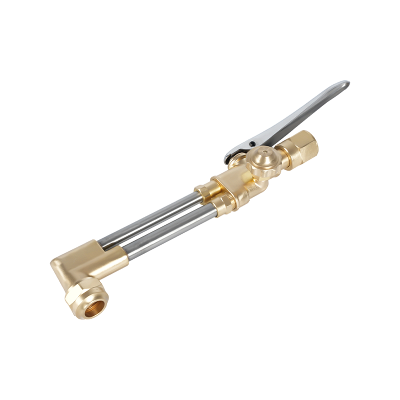
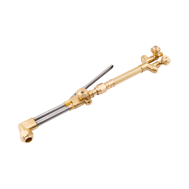
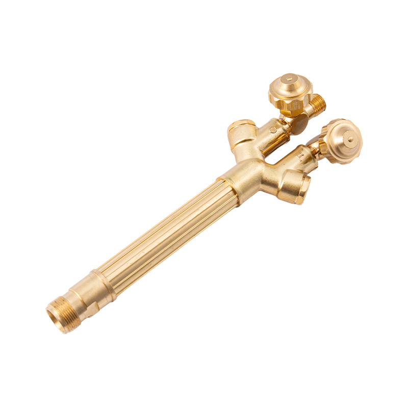
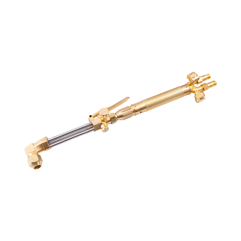
A two-piece torch splits into a handle and a cutting attachment that joins it with two tubes and a union nut. On most designs the handle holds no mixing chamber at all — it is a pair of valve bodies with stems, packings and knobs.
Needle valves
The fuel and oxygen knobs meter preheat gas and are adjusted together: open the fuel slightly, light it, then add oxygen until the bright inner cone shortens into a neutral flame. Diagrams usually draw these as two small circles. In practice they are among the first parts replaced, because over-tightening scores the stem seat and the flame stops responding to adjustment.
Mixer or injector
Sitting at the base of the attachment, the mixer is where the drawing earns its keep. Equal-pressure torches combine the two gases at similar pressures. Injector torches use a small oxygen jet to draw fuel gas into the chamber, keeping the mixture stable when acetylene pressure sags. A worn mixer shows up as a flame that changes character when the torch is tilted, or a pop on light-back.
Cutting oxygen lever
The lever opens a valve admitting a high-volume oxygen stream straight into the centre of the tip, bypassing the mixer. It should open fully and close sharply. A lever that creeps produces a ragged edge and an oversized kerf without any other obvious cause.
Tip nut and seat
The nut clamps a tapered seat against a matching taper on the tip. This is a metal-to-metal seal, not a thread seal. A single nick on the seat lets oxygen bleed into the preheat passages and creates the familiar complaint that the tip keeps popping no matter how the valves are set.
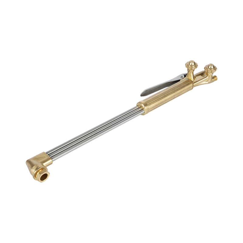 B400 Heavy-Duty Handheld Oxygen Acetylene Cutting TorchDual-tube handheld torch for demanding cutting up to 300 mm, compatible with acetylene and propane and 1502/1503 nozzles for heavy fabrication work.View Product →
What the Tip Looks Like in Cross-Section
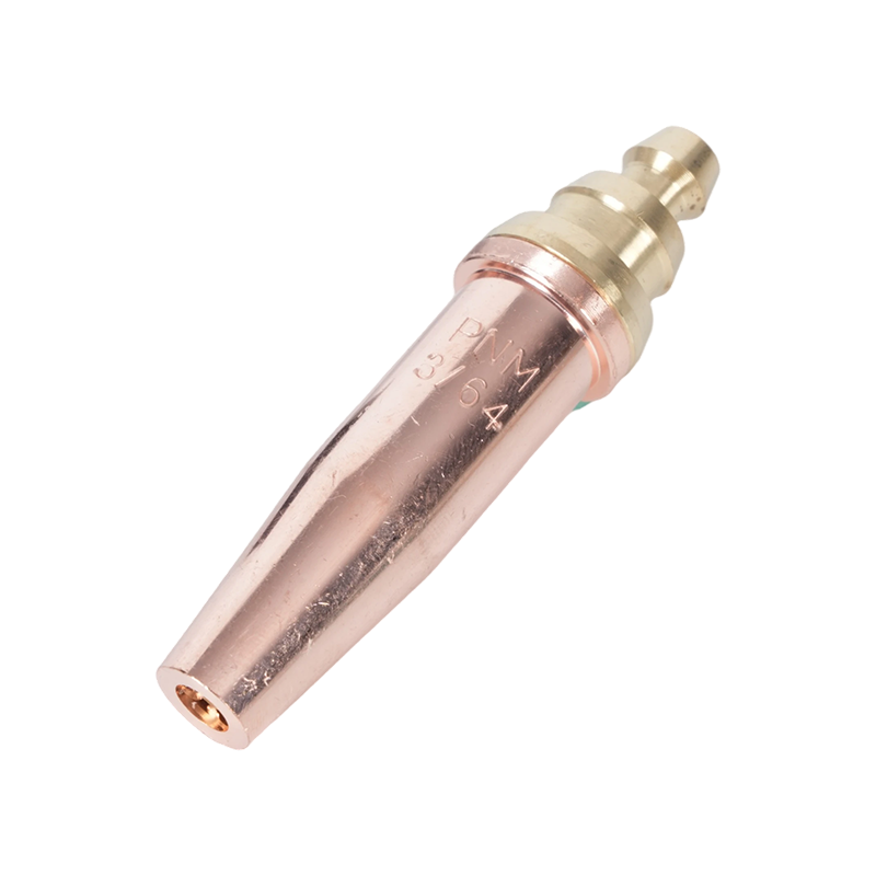
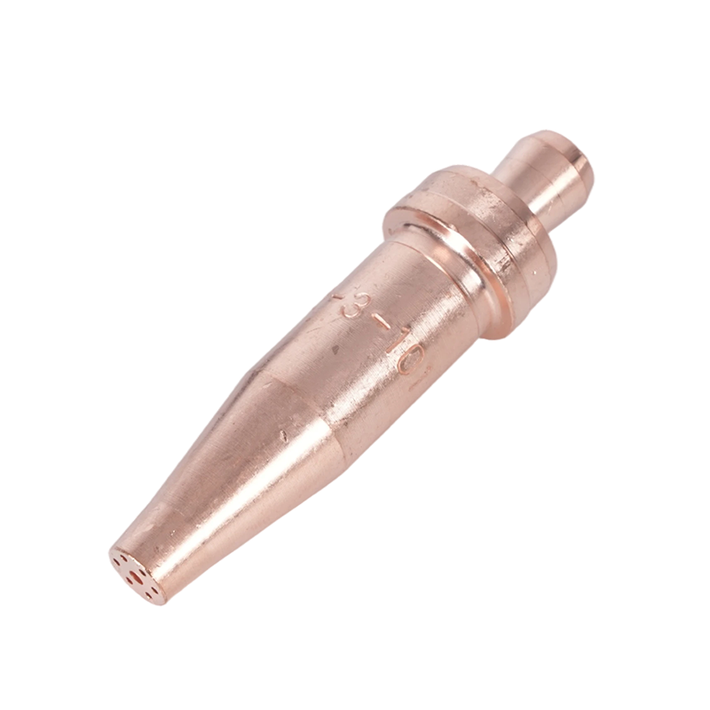
Zoom in and the diagram becomes a small assembly: a hex or knurled body, a tapered seat, a ring of preheat orifices — commonly four to six, more on large sizes — and one central cutting orifice. The tip number is stamped on the body, and that number governs the whole setup.
Cutting is not melting. The preheat flames raise a spot of steel to its ignition temperature, roughly 870 °C (1,600 °F), and the oxygen jet then oxidizes the iron and blasts the oxide out of the kerf. That is why preheat orifice condition matters more than most operators expect: a partly blocked hole makes one side of the cut run cold, and the kerf curves away from the line.
Matching Tip Size, Thickness and Pressure
Published charts vary by manufacturer, fuel gas and tip series, but the relationship is consistent: tip number rises with plate thickness, cutting oxygen pressure rises with tip number, and travel speed falls.
| Plate thickness | Typical tip number | Cutting oxygen pressure |
|---|---|---|
| 3 mm (1/8 in) | 000 | 20–25 psig |
| 6 mm (1/4 in) | 00 | 20–25 psig |
| 10 mm (3/8 in) | 0 | 25–30 psig |
| 20 mm (3/4 in) | 1 | 30–35 psig |
| 25 mm (1 in) | 2 | 35–40 psig |
| 50 mm (2 in) | 3 | 40–45 psig |
| 100 mm (4 in) | 5 | 45–55 psig |
Two practical notes. Propane tips carry larger preheat passages and consume more oxygen than acetylene tips of the same number, so a chart written for one fuel is invalid for the other. And every pressure in any chart is measured at the regulator through a given hose length; on runs much longer than 25 feet, add a little delivery pressure and re-check the flame before blaming the tip.
Four Details the Drawing Usually Leaves Out
- Arrestor placement. Regulator-end arrestors protect the cylinders; torch-end check valves protect the operator. Many diagrams show one and not the other. On a busy bench, fit both.
- Tip standoff. The inner cone should sit 1.5 to 3 mm off the plate. Contact overheats the tip and starts a pop cycle that no valve adjustment will cure.
- Drag and lead angle. Drag lines lean with the direction of travel, and a 10 to 15 degree lead compensates on thicker plate. A diagram showing a perfectly vertical kerf is showing an ideal, not a result.
- Orifice cleaning. Preheat holes are cleaned with a correctly sized tip cleaner, never a drill bit. Drilling removes the metering edge and retires the tip.
Gas handling discipline belongs in the same drawing. Our guide to safety precautions when using a cutting torch covers leak testing, lighting sequence and shutdown in the order they should happen.
Specifying a Torch Against the Diagram
Once the flow is clear, buying decisions get simpler. Three questions decide most of it. What duty class does the work demand — heavy, medium or light, reflected in wall thickness, valve stems and forged brass versus aluminium handles? Which regional standard do the tips and seats follow, since US, Australian, British and Japanese patterns do not interchange? And who supplies consumables — tips, nuts, O-rings and arrestor elements — five years from now?
For buyers sourcing from a manufacturer, the diagram doubles as a specification sheet. A supplier able to forge, machine and assemble in-house can hold tolerances on the seat taper and mixer jet, the two features that most affect cut quality. Our own production in Ningbo covers die making, forging, surface finishing, CNC machining and inspection under one roof, with roughly two decades in welding and cutting tools, and we machine to customer drawings when a standard pattern does not fit.
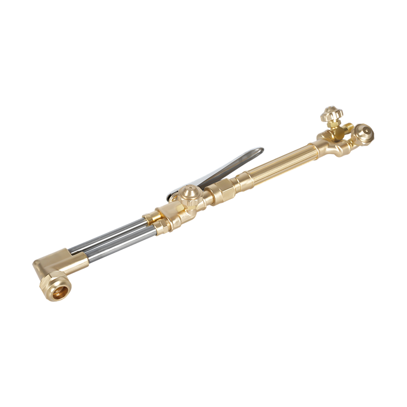 A217 Oxy-Acetylene/Propane Heavy-Duty Cutting Torch KitHeavy-duty kit with A212 cutting attachment and A211 handle, rated to 200 mm and compatible with oxyacetylene or propane for industrial cutting, brazing and heating.View Product →
If you are matching a torch set to an existing hose, regulator and tip inventory, send the drawing or the part numbers through our contact page and we will confirm seat type, thread form and tip compatibility before quoting.
Print the diagram, then annotate it: write the actual regulator pressures, the tip number you use on each plate thickness, and the date the arrestors were last inspected. A drawing that carries your own numbers stops being a poster and starts being a setup sheet — and the next time a cut runs rough, the answer is usually one line away.