Two things go by the name "cable welding" in the industry, and confusing them wastes time. The first is the welding cable itself — the heavy, flexible conductor that carries current from a welding machine to the electrode and back. The second is the process of welding or brazing cables together, a task that shows up in electrical infrastructure, shipbuilding, and heavy industrial maintenance. Both matter, and both have real consequences when handled incorrectly.
This guide covers the construction, selection, and safe use of welding cables, along with where gas welding equipment enters the picture for joining cable terminations and conductors.
Content
What Cable Welding Actually Means
In most technical and commercial contexts, "welding cable" refers to the secondary circuit conductors used in arc welding systems. These are the flexible leads that connect the welding power source to the electrode holder on one end and to the workpiece ground clamp on the other. Without them, no current flows, no arc forms, and no welding happens.
The second meaning is more literal: the act of welding or brazing the ends or bodies of cables together — joining copper conductors, terminating lugs onto heavy-gauge leads, or heat-splicing insulated cable bundles. This appears frequently in power infrastructure work, mining operations, naval construction, and anywhere large-gauge conductors need a permanent, low-resistance connection rather than a mechanical connector.
Both applications share the same fundamental challenge: high current, high heat, and demanding physical environments that punish poorly chosen or poorly maintained equipment.
How Welding Cables Are Constructed
A welding cable is not a standard electrical cable pressed into service. It is engineered from the ground up for repeated flexing, heat exposure, weld spatter, and rough handling on job sites where nothing stays clean or stationary for long.
The conductor is always fine-stranded copper. Where a standard building wire might use a handful of thick strands, a welding cable uses hundreds of hair-thin copper strands bundled together. This is what gives the cable its characteristic flexibility — it bends without kinking, coils without cracking, and uncoils without memory. The two most common strand classes are Class K (30 AWG strands, the industry standard for manual welding and general portable power) and Class M (34 AWG strands, the more flexible option used in robotic welding arms, tight-space installations, and pipeline work).
The insulation jacket is thermoset, not thermoplastic. EPDM (ethylene propylene diene monomer) and neoprene are the dominant materials. Both resist weld spatter, abrasion, moisture, and UV exposure. EPDM handles temperature extremes better and maintains flexibility in cold conditions. Neoprene offers stronger resistance to oils and petroleum-based fluids. Neither performs well in prolonged contact with gasoline or similar hydrocarbons — an important consideration on job sites where fuel and welding equipment share the same space.
Most welding cables are rated at 600 volts, though 100-volt-rated cables also exist for specific low-voltage applications. The operating temperature rating is typically 90°C or 105°C depending on the insulation compound used.
Choosing the Right Welding Cable for the Job
Three variables drive cable selection: ampacity, total circuit length, and insulation type. Getting any of them wrong results in voltage drop, overheating, accelerated cable degradation, or outright failure under load.
Ampacity is the maximum current a cable can carry without exceeding its rated temperature rise. A 2/0 AWG cable handles approximately 200 amps at a 50-foot total circuit length. A 4/0 AWG cable handles approximately 300 amps at the same length. These are not rigid maximums — duty cycle matters. A cable rated for 200 amps at 60% duty cycle will overheat if run continuously at that current.
Cable length compounds the problem. Resistance increases with length, which means voltage drop increases and effective power at the arc decreases. The practical rule is to increase cable gauge by at least one AWG for every 50 additional feet of total circuit length beyond the baseline. A 300-amp welder with 100 feet of total cable needs 3/0 AWG, not the 2/0 AWG that would suffice at 50 feet. When in doubt, size up — a larger cable runs cooler, lasts longer, and maintains arc quality.
Insulation type comes down to environment. EPDM is the right choice for most welding operations, especially outdoor work or cold-climate applications. Neoprene is the better option where cable contact with oils, cutting fluids, or lubrication is likely. In environments where both gas cutting equipment and arc welding systems operate in close proximity — a common setup in fabrication shops and shipyards — choose insulation that can handle incidental heat exposure from torch work as well as weld spatter.
| Cable AWG | Approx. Ampacity | Typical Application |
|---|---|---|
| 2 AWG | Up to 150A | Light-duty MIG, hobbyist arc welding |
| 1/0 AWG | Up to 200A | Medium-duty MIG/TIG, general fabrication |
| 2/0 AWG | Up to 250A | Heavy-duty stick welding, structural steel |
| 3/0 AWG | Up to 300A | Industrial arc welding, long cable runs |
| 4/0 AWG | Up to 400A | High-output welding, pipeline, shipbuilding |
Where Gas Welding Equipment Fits In
Arc welding and oxy-fuel gas equipment often operate side by side, and there are specific tasks where gas equipment takes the lead — particularly in cable termination and lug brazing work.
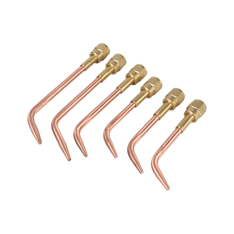
Attaching copper lugs to large-gauge welding cables requires controlled, concentrated heat to flow solder or braze filler metal into the lug barrel and strand bundle without burning back insulation or oxidizing the copper. A resistance crimp handles this mechanically, but for high-conductivity permanent joints — especially in mining, naval, and heavy industrial settings — a gas-heated braze joint delivers lower resistance and better long-term reliability than a crimped connection under repeated thermal cycling.
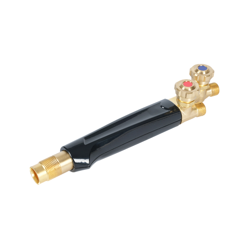
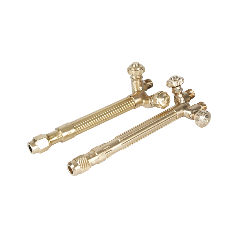
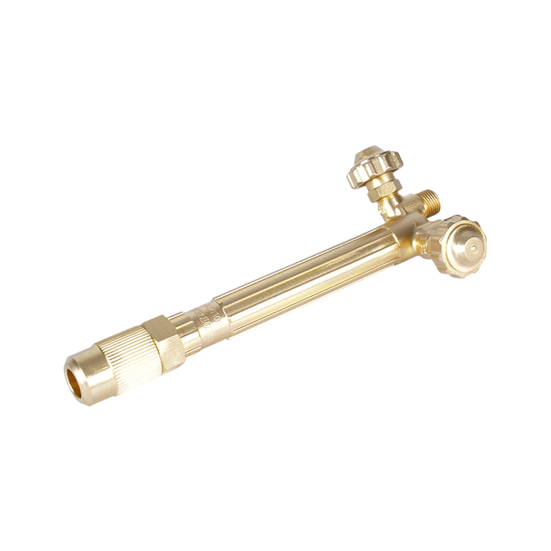
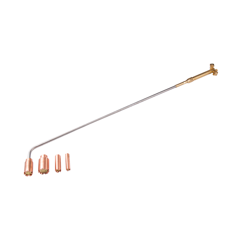
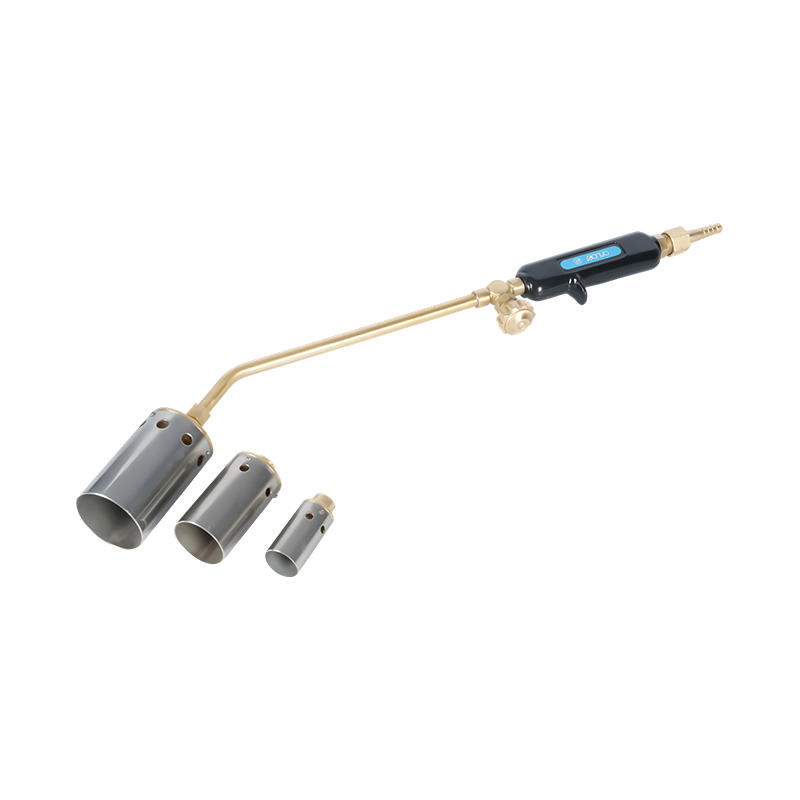
Oxy-acetylene heating torches built for precise cable brazing and joining work provide the localized, adjustable heat output needed for this process. The ability to dial in flame size and heat intensity means the joint area reaches brazing temperature without overheating adjacent insulation — a balance that's difficult to achieve with larger cutting or welding flames. For fieldwork where portability matters, a portable gas welding and heating torch for fieldwork provides the same precision in a compact format suited to confined spaces and remote sites.
Gas heating equipment is also used to pre-heat cable termination areas before tinning, to remove corroded or seized cable lugs on aging equipment, and to soften and re-form outer insulation jackets during cable repair operations where full replacement is impractical.

Cable Welding Safety: What OSHA Requires
Welding cables carry high current in demanding environments, and regulatory requirements exist for a reason. Under OSHA's construction industry arc welding standard (29 CFR 1926.351), all arc welding and cutting cables must be fully insulated, flexible, and rated for the maximum current of the work in progress. The standard also specifies that cable must be free from repair or splice for at least ten feet from the electrode holder end. When cables are joined, the connectors must be insulated and rated to at least the same capacity as the cable itself.
Cables with damaged insulation, exposed bare conductors, or compromised splices must be taken out of service. OSHA's general industry standard goes further — it requires replacement rather than repair for damaged welding leads in most circumstances. Attempting to tape over a cut or abrasion in the insulation and continue using the cable is both a compliance violation and a genuine electrocution risk.
Additional safety requirements specific to cable welding environments include:
- Welders must not coil or loop electrode cables around any part of their body while welding
- Ground return cables must have current-carrying capacity equal to or greater than the total output of the welding units they serve
- All arc welding machine frames must be grounded through the circuit cable or a separate grounding conductor
- Cables must be kept clear of heat sources, sharp edges, and pinch points that could damage insulation
When gas equipment operates in the same space as welding cables and electrical welding systems, an additional layer of safety is required. Oxy-fuel lines and electrical leads must be routed separately to prevent gas hoses from being damaged by arc spatter or cable insulation from being degraded by gas leaks. Flashback arrestors that protect gas lines in high-current welding environments are essential equipment wherever gas torches and arc systems share the workspace — a flashback event near an unprotected gas supply line is far more dangerous than either hazard in isolation. For a complete overview of torch-side safety requirements, the guide on cutting torch safety precautions every operator should follow covers the full protocol.
Inspection and Maintenance of Welding Cables
Welding cables fail gradually, then suddenly. The gradual phase — cracking insulation, copper strand fatigue, loosening connectors — is entirely catchable with a disciplined pre-use inspection. The sudden phase typically involves a short circuit, an arc flash, or an equipment fault that stops production and can injure personnel.
Before each shift, inspect the full length of both the electrode lead and the work lead for insulation cracks, cuts, or abrasion damage. Pay particular attention to cable ends near connectors and holders, where mechanical stress concentrates. Check all connections for tightness and corrosion — a loose lug or a green-tinged copper connection introduces resistance that generates heat and degrades arc quality.
The insulation on EPDM and neoprene cables is resilient but not indestructible. Common damage sources include rolling equipment running over cables, cables draped over sharp structural edges, and prolonged contact with grinding sparks or cutting torch heat. Routing cables through protective sleeves in high-traffic areas and keeping them off the floor where possible significantly extends service life.
Replace cables on schedule, not just on failure. A cable that has been in heavy daily service for two or more years has accumulated significant conductor strand fatigue even if the outer jacket looks intact. The resistance of a fatigued cable is measurably higher than a new cable of the same size, and the degradation in arc performance is real before any visible damage appears. Keeping spare leads on site means a cable swap takes minutes rather than shutting down an entire welding station.