Content
Why Stainless Steel Demands a Different Approach
Stainless steel resists corrosion because of its chromium content — typically 10% or higher — which forms a passive oxide layer on the surface. That same layer is what makes it unforgiving in the welding shop. Heat is the central problem: stainless steel conducts heat roughly a third as efficiently as mild steel, which means the energy from the arc stays concentrated near the weld zone instead of dispersing. The result is rapid heat buildup, increased risk of warping, and — if temperatures are pushed too high — a phenomenon called sensitization, where chromium carbides precipitate at grain boundaries and the metal loses its corrosion resistance precisely where you need it most.
Contamination is the second major variable. A carbon steel wire brush, a grinding disc that previously touched mild steel, or oil from bare hands on the base metal can all introduce foreign material into the weld zone, seeding porosity or eventual rusting. Stainless steel welding is a process where preparation accounts for most of the final weld quality — getting the heat and contamination variables under control before the arc starts is what separates clean, corrosion-resistant welds from ones that fail in service.
The good news is that the process is learnable. TIG, MIG, and stick welding all work on stainless, each suited to different material thicknesses and application contexts. Understanding which process to use — and why — is the first decision to get right.
Choosing the Right Welding Process
Three processes dominate stainless steel welding in practice. Each has a defined sweet spot.
TIG welding (GTAW) is the precision choice. A non-consumable tungsten electrode produces the arc while filler rod is fed manually, giving the welder complete independent control over heat input and filler deposition rate. Run on DCEN (direct current electrode negative) with 100% argon shielding, TIG produces the cleanest welds on stainless — virtually spatter-free, excellent bead appearance, and minimal heat-affected zone when technique is good. It is the standard for thin sheet (under 3 mm), pipe work, food-grade equipment, and any application where the finished weld will be visible. The trade-off is speed: TIG is slow, and the manual dexterity required takes practice to develop.
MIG welding (GMAW) suits heavier sections and higher production volumes. The wire feeds continuously, which increases deposition rate significantly compared to TIG. On stainless, the push technique is standard — holding the gun at roughly 90 degrees with a 5–15 degree travel angle — which maintains better gas coverage over the puddle. Shielding gas selection is more complex than for carbon steel: pure CO₂ is damaging to stainless, and pure argon produces a cold, sluggish arc. The most common working gases are a tri-mix of 90% helium / 7.5% argon / 2.5% CO₂ for short-circuit transfer, or a 98% argon / 2% oxygen blend for spray arc transfer. Getting the gas mix wrong is one of the most common causes of poor stainless MIG results.
Stick welding (SMAW) is the most forgiving of the three in terms of surface preparation, and it is viable for field work or thicker sections where TIG or MIG equipment is impractical. The electrodes (E308, E316, or E309 for dissimilar metal joints) contain flux that generates its own shielding, eliminating the need for external gas. The heat input is higher and less controllable than TIG, which makes warping on thin sections a real risk. For structural repairs and heavy fabrication, stick is a practical and effective option.
| Process | Best Thickness Range | Shielding Gas | Heat Control | Skill Level |
|---|---|---|---|---|
| TIG (GTAW) | Thin to medium (<3 mm ideal) | 100% Argon | Excellent (foot pedal / pulse) | High |
| MIG (GMAW) | Medium to thick (3 mm+) | Tri-mix or Ar/O₂ blend | Good (wire speed / voltage) | Moderate |
| Stick (SMAW) | Thick sections / field repair | None (flux-shielded) | Limited | Moderate |
Surface Preparation and Contamination Control
Preparation for stainless welding is stricter than for carbon steel, and the rules are worth treating as non-negotiable. The first is tool segregation: keep a dedicated set of brushes, grinders, and clamps for stainless only. Once a wire brush or abrasive disc contacts carbon steel, it carries iron contamination that will transfer to stainless on contact, embedding particles that corrode and undermine the passive layer. Label the tools and enforce the separation consistently.
The surface itself needs to be clean of oil, grease, paint, ink marks, and oxidation before welding. Acetone or a dedicated stainless degreaser on a clean cloth handles organic contamination. For oxidation or mill scale on cut edges, use an iron-free abrasive or a flap disc rated for stainless — never a disc that has touched carbon steel. Cutting method also matters: plasma cutting and laser cutting are preferred over oxy-acetylene cutting for stainless because they avoid carbon contamination at the cut edge. If oxy-acetylene cutting is unavoidable, the edge must be ground back before welding.
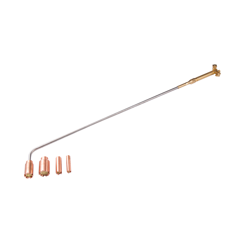
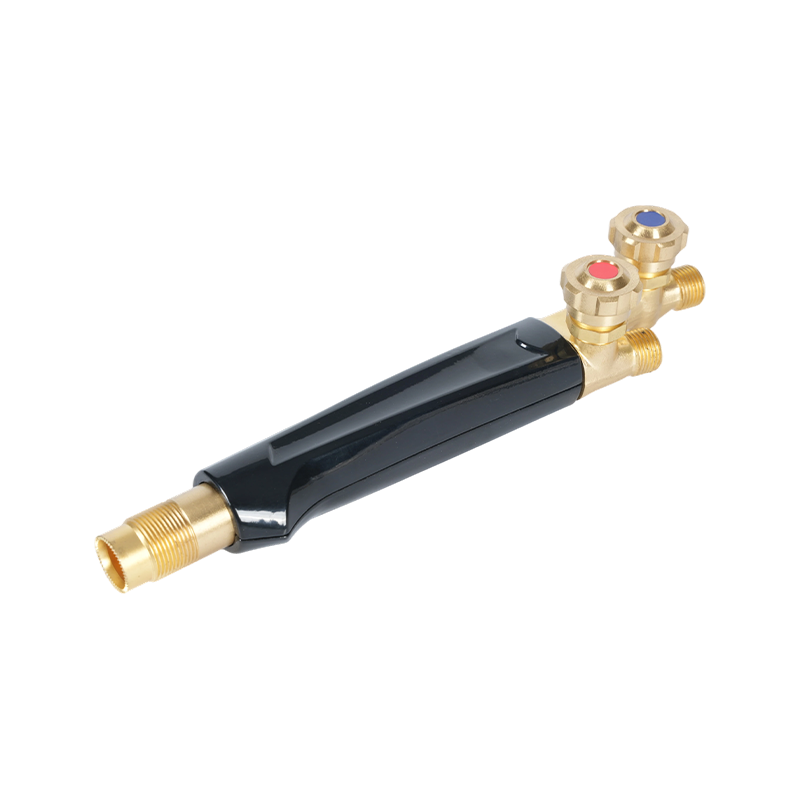
Joint fit-up should be tight. Root gaps exceeding 1.5 mm increase the risk of burn-through and inconsistent root penetration, particularly on thin material. Tack welds at intervals of 50 mm or less hold the joint in position and reduce distortion during the main weld run. A cutting attachment and torch handle system rated for precision gas control is the appropriate tool for any oxy-fuel cutting or pre-heat work that precedes stainless welding, ensuring consistent flame delivery without contaminating the cut zone.

Heat Control: The Core Technical Challenge
Heat management in stainless steel welding comes down to two objectives: achieving full fusion without overheating the base metal, and distributing heat evenly to prevent distortion. Both require deliberate technique rather than relying on the machine to compensate.
Interpass temperature is the key control variable on multi-pass welds. The maximum interpass temperature for austenitic stainless steels (the 304 and 316 grades most commonly encountered) is generally held to 150°C (300°F). Exceeding this risks carbide precipitation and sensitization. On TIG, a pulse setting reduces average heat input without sacrificing penetration — the peak current achieves fusion while the background current allows the metal to cool slightly between pulses. On MIG, wire feed speed and voltage adjustments achieve a similar effect; a narrower wire diameter also reduces required current for a given penetration depth.
For longer weld runs, skip welding (moving to a different section of the joint periodically rather than welding continuously in one direction) distributes heat more evenly and reduces the thermal gradient that causes warping. Backstep welding — welding short increments in the direction opposite to the overall weld progression — is another effective technique for managing heat buildup in confined sections. Chill bars, copper backing plates, and heat sinks placed adjacent to the weld zone also absorb excess energy and keep interpass temperatures in range.
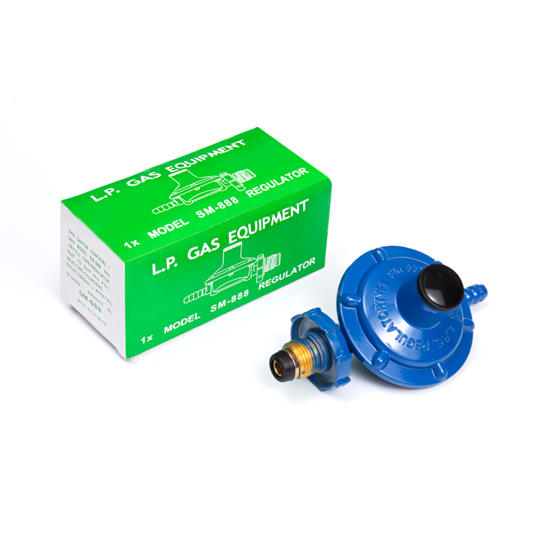
Accurate gas pressure at the regulator is as important as the welding technique itself. Insufficient shielding gas flow leaves the weld pool unprotected, causing oxidation and porosity. Excessive flow creates turbulence that draws atmospheric air into the shield. A calibrated gas pressure regulator matched to the welding process and flow rate requirements is the baseline control for maintaining consistent gas coverage throughout the weld.
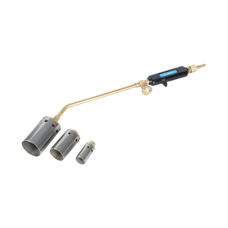
Equipment Essentials: Torches, Tips, and Safety
The torch and its consumables are where technique and equipment intersect. For oxy-fuel work adjacent to stainless fabrication — pre-heating ferritic or martensitic grades, post-weld stress relief, or cutting operations on the workpiece before welding — torch quality and maintenance directly affect outcome. A well-maintained heating torch designed for precise flame control in metalworking applications delivers the controlled, consistent heat input that stainless requires, without the surges or backfires that contaminate the work area or damage the base metal.
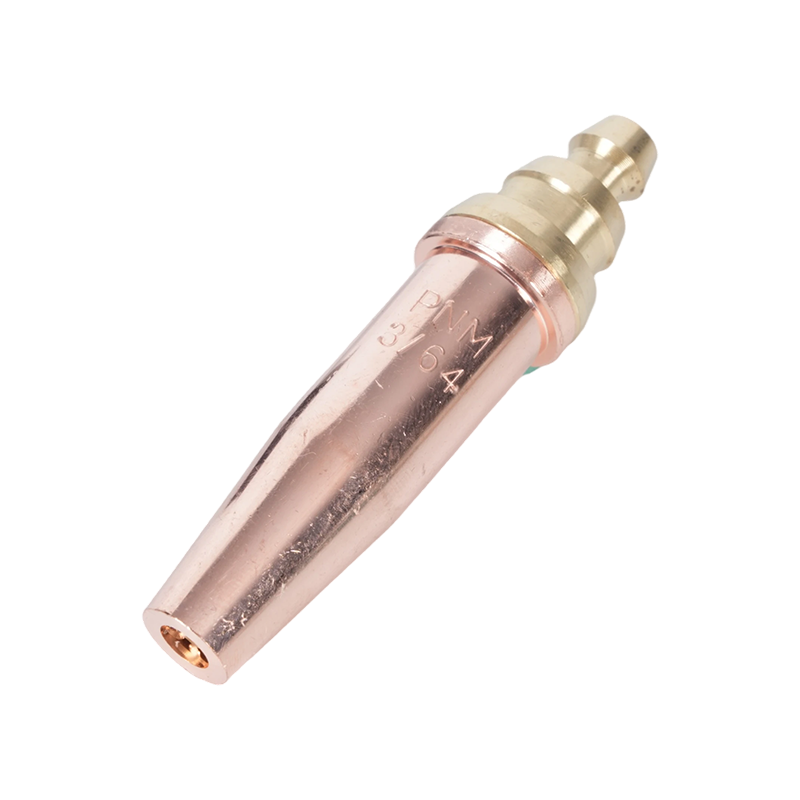
Torch tips determine flame characteristics. The correct tip size for the material thickness and gas type affects both heating efficiency and the quality of the cut edge if cutting is involved. Cutting torch tips and nozzles selected for the specific gas and material combination ensure a clean, oxidation-free edge that requires minimal rework before welding. Using an undersized tip for thick stock causes incomplete cutting; an oversized tip introduces excessive heat that distorts the surrounding material.
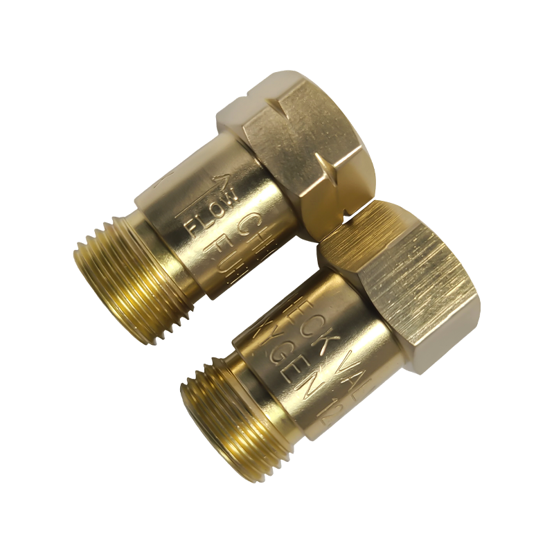
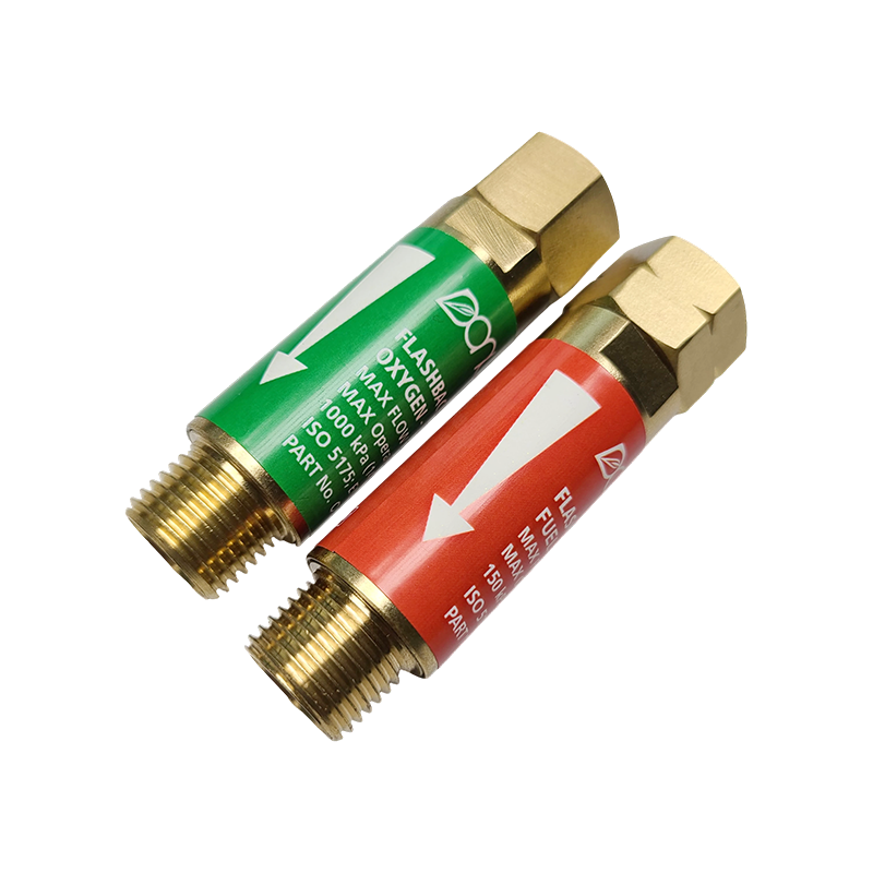
Flashback — the condition where the flame propagates back into the torch body or hose — is a serious safety risk in any oxy-fuel setup, and stainless fabrication environments are no exception. Flashback arrestors installed at the torch and regulator connections interrupt reverse flame travel before it reaches the hose or gas supply. These devices are a mandatory safety component in professional welding environments, not an optional upgrade. Regulatory guidance from bodies including the American Welding Society reinforces their use as standard practice on any oxy-fuel torch system. For a comprehensive overview of welding process selection and filler metal compatibility for stainless applications, NS ARC's complete welding guide covering shielding gas, wire selection, and best practices for stainless is a useful reference point for specifiers and fabricators.