Content
What a Welding Nozzle Does — and Why It Matters
Every weld or cut starts with a flame or arc — but neither can perform reliably without a nozzle directing what surrounds it. The nozzle is the final point through which shielding gas, fuel gas, or oxygen exits the torch body and reaches the work zone. Its job sounds simple. In practice, it determines everything from weld porosity to cut edge quality to how often you're stopping to clean spatter off your equipment.
In gas-shielded arc welding processes like MIG/GMAW, the nozzle creates a protective envelope of shielding gas around the weld pool, blocking atmospheric oxygen and nitrogen from contaminating the molten metal. Without adequate gas coverage, the weld oxidizes, porosity appears, and mechanical properties drop. In oxy-fuel cutting and welding, the nozzle controls the geometry of the flame itself — determining the ratio of preheat flame to cutting oxygen stream and the spread of heat across the workpiece.
A worn, clogged, or incorrectly sized nozzle doesn't just reduce quality — it multiplies consumable costs and downtime. Spatter buildup restricts gas flow, causing turbulence that undermines shielding coverage. A nozzle bore that's too small for the application raises back-pressure, disrupting the flame or arc. Understanding the nozzle is, in practice, understanding half of what controls your process stability.
Nozzle Types by Welding Process
Nozzles are not interchangeable across processes. The correct starting point for any nozzle selection is identifying the welding or cutting process being used — each has different nozzle geometry, material requirements, and function.
MIG / GMAW nozzles are cylindrical or shaped consumables that attach to the front of the MIG gun and surround the contact tip. Their primary function is to direct shielding gas — typically argon-rich mixtures or CO₂ — over the weld pool. They come in slip-on and threaded attachment styles. Slip-on nozzles mount and remove faster, which matters on high-production lines; threaded nozzles provide a more secure gas seal and are less likely to loosen under vibration. Both styles are available in standard and heavy-duty constructions, the latter featuring thicker walls and insulators rated for 400–600 amp applications.
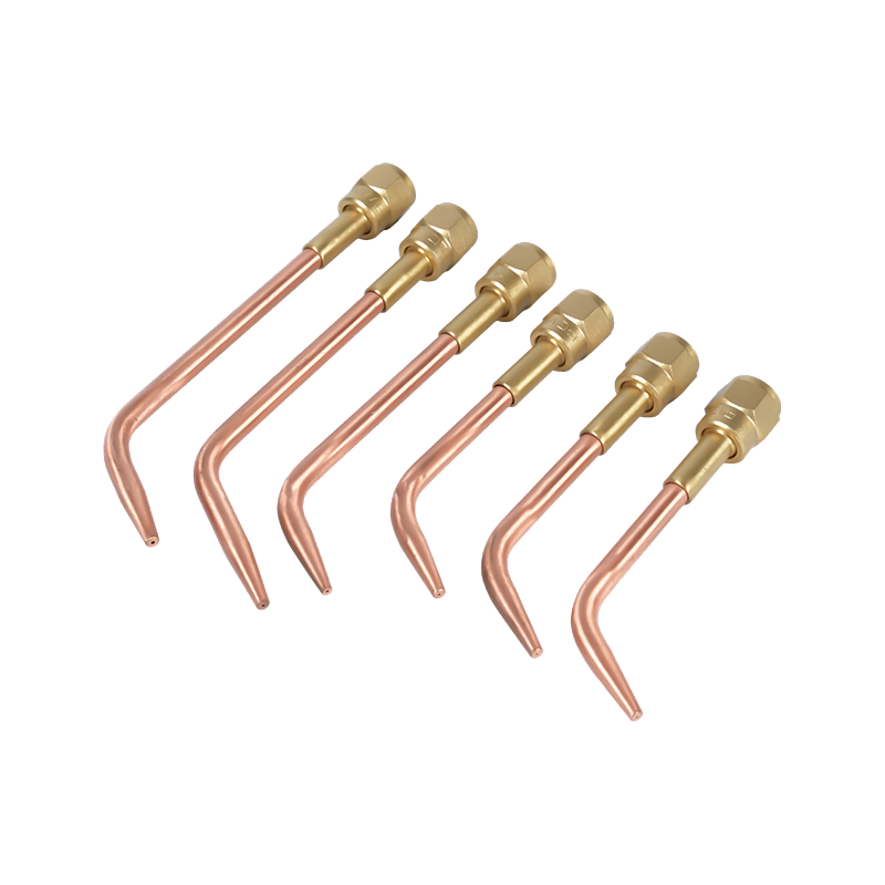
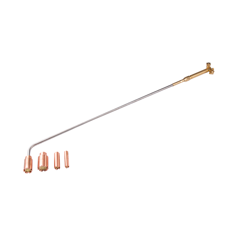
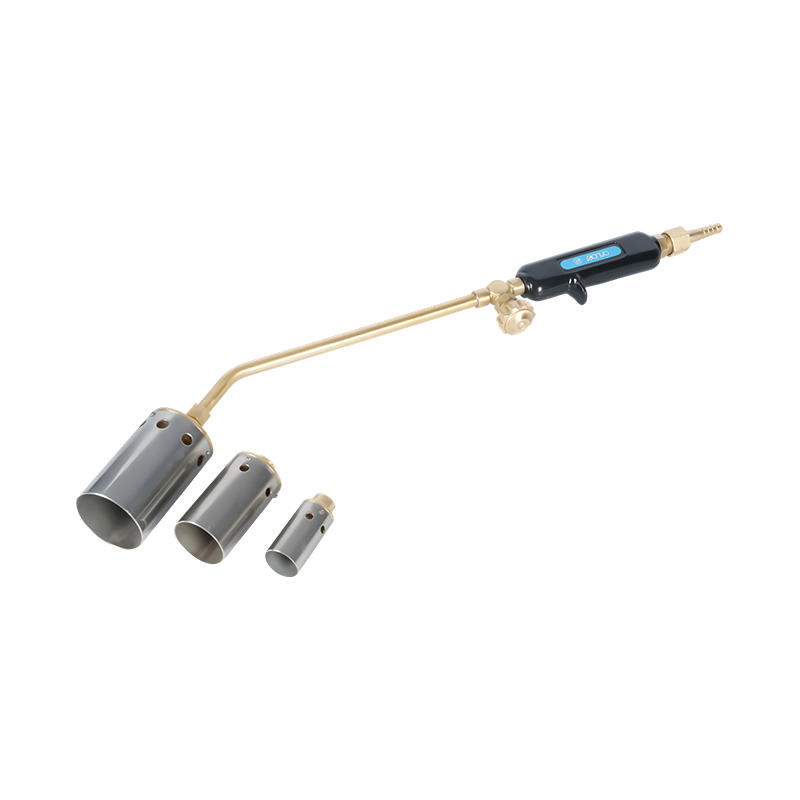
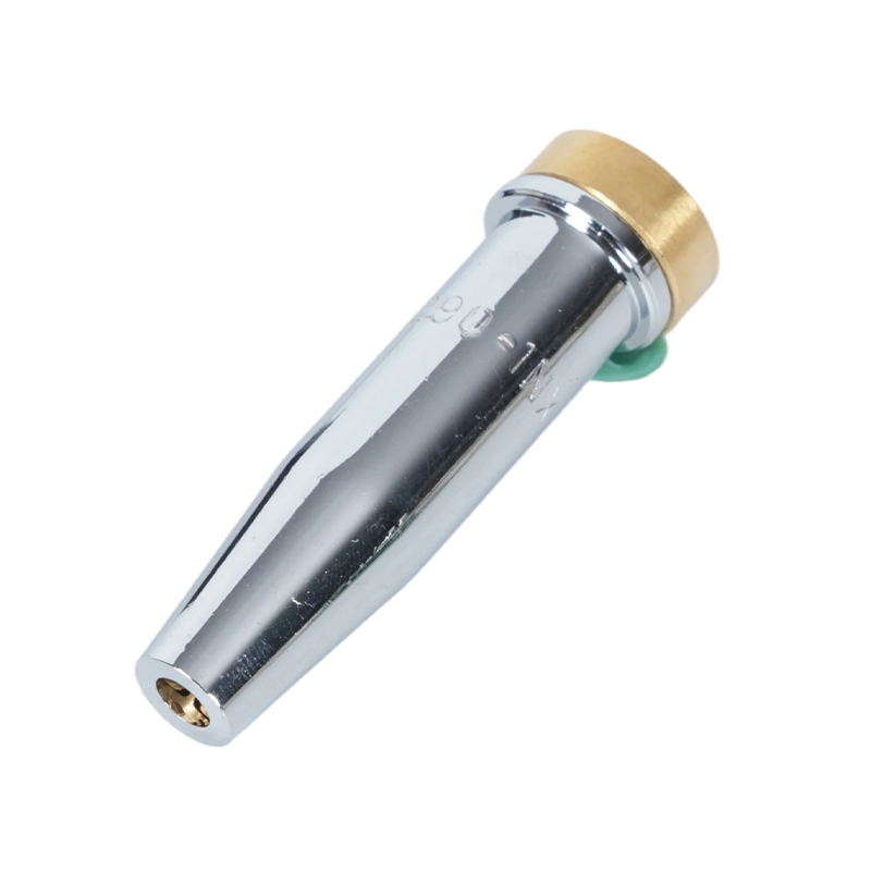
Oxy-fuel cutting and welding nozzles — often called cutting tips or torch tips — function differently. Rather than shielding a weld pool, they mix and direct fuel gas (acetylene or propane) and oxygen to produce a precise, high-temperature flame. Cutting tips have a central high-pressure oxygen orifice surrounded by preheat flame ports; the preheat flame brings the steel to ignition temperature, and the cutting oxygen jet then oxidizes and ejects the molten material. Acetylene cutting torch tips for oxy-fuel applications deliver the hottest flame of any common fuel gas (around 3,500°C), making them the first choice for cutting thicker steel and for applications requiring fast preheat. Propane cutting torch tips designed for stable flame delivery operate at a lower flame temperature but offer a wider, more even heat envelope — particularly effective for heating, bending, and cutting thinner sections where a concentrated acetylene flame would cause localized distortion. For applications focused purely on heat rather than cutting, heating tips for controlled flame distribution feature multiple preheat ports arranged to spread heat evenly across a broader surface area, without the central cutting oxygen channel.
TIG / GTAW nozzles (also called gas cups or collet bodies) direct argon shielding gas around the tungsten electrode. They are typically made from alumina ceramic, glass, or gas lens configurations. Unlike MIG nozzles, TIG cups do not contact the work and are primarily chosen based on tungsten diameter, joint access, and the need for laminar versus diffused gas flow. Gas lens assemblies — which use a mesh insert to create a more laminar gas column — are preferred for precision work and out-of-position welding where consistent shielding is critical.
Nozzle Shapes and Bore Sizes Explained
Within each process category, nozzle geometry has a direct effect on gas coverage, joint accessibility, and spatter clearance. For MIG welding, four shapes cover most applications:
- Cylindrical (straight): A constant-diameter bore from base to tip. Offers maximum gas flow volume and is the standard choice for flat or horizontal welds with no access restrictions. Bore sizes range from ⅜" to ⅞" (approximately 10–22 mm), and as a general rule, bore diameter should increase with amperage — larger bores support higher gas flow rates needed to cover wider, hotter weld pools.
- Bottleform (bottleneck): Steps down to a smaller outer diameter near the working end. The reduced profile improves visibility and access to confined joints. Particularly well suited for automated and robotic welding because the narrow tip clears fixtures more easily and can be cleaned more efficiently by torch reaming stations.
- Short and long taper: A gradual taper from base toward the tip. Good joint access with better gas coverage than the bottleform. Long tapers are preferred for pipe welding and corner joints; short tapers balance accessibility with gas flow efficiency for general fabrication.
- Conical: A wider, outward-flaring profile at the tip. Maximizes the gas coverage area — useful for wider weld pools, higher heat inputs, and when welding zinc-coated metals that produce large, explosive spatter. The wider mouth also makes reaming with a torch cleaning station more effective in robotic setups.
For oxy-fuel cutting tips, the bore geometry determines the cutting oxygen stream shape and the preheat pattern. Tip size numbers correspond to the thickness of material being cut — larger numbers indicate larger oxygen orifices and higher gas consumption rates appropriate for thicker steel. According to the AWS specification for welding shielding gases and their classifications, gas composition and flow rate are standardized parameters — meaning nozzle bore geometry must be matched to the gas type and pressure in use, not selected in isolation.
Material Guide: Brass, Copper, and Plated Options
Nozzle material governs two things: spatter resistance and thermal management. These two properties often pull in opposite directions depending on the application, which is why no single material dominates all use cases.
Brass offers better spatter resistance than bare copper in lower-amperage applications (100–300 amps). Spatter does not adhere as readily to brass surfaces, meaning longer intervals between cleaning. However, brass has a lower softening point than copper — at higher amperages or extended arc-on times, a brass nozzle can deform under sustained heat, making it unsuitable for heavy-duty work. When used as an insert within a copper body, brass helps maintain the nozzle's internal diameter over time, extending service life in moderate-heat applications.
Copper conducts heat more effectively than brass, which makes it the better choice for sustained high-heat work (above 300 amps) and for longer welding cycles. Copper nozzles absorb and dissipate heat faster, reducing the risk of thermal distortion. Heavy-duty copper nozzles — with thicker walls and insulators — are the standard for 400–600 amp applications in structural fabrication and heavy plate welding. For oxy-fuel cutting tips, copper or high-grade copper alloys are the standard material precisely because of their ability to withstand the extreme temperatures of the cutting flame without deforming or eroding the orifice geometry.
Nickel-plated and chrome-plated nozzles combine a copper core with a surface coating that is more resistant to spatter adhesion than either bare copper or brass. The plating also provides some thermal insulation benefit. Their primary application is in robotic and automated welding, where long, uninterrupted welding cycles are routine and minimizing cleaning downtime directly impacts throughput. The longer service life justifies their higher upfront cost in high-volume production environments.
Ceramic nozzles represent a newer category, primarily used in TIG welding and some specialized MIG applications. Their non-conductive surface means that spatter cannot electrically bridge from the nozzle to the contact tip — a failure mode that causes current flow through the nozzle and rapid degradation. Ceramic TIG cups also withstand direct contact with hot workpieces without melting, making them useful for welding in tight grooves.
Three Steps to Choosing the Right Nozzle
Selection becomes straightforward when it follows a fixed sequence rather than trying to evaluate all variables simultaneously.
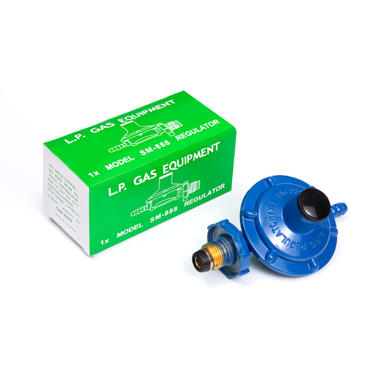
Step 1 — Identify the process and its operating parameters. Determine whether the application is MIG/GMAW, oxy-fuel cutting, oxy-fuel heating, or TIG. For arc processes, establish the operating amperage range. For oxy-fuel processes, identify the fuel gas (acetylene vs. propane) and the thickness of the material being cut or heated. These parameters immediately narrow the field: a 150-amp MIG application calls for a standard brass or copper nozzle; a 500-amp robotic MIG cycle calls for a heavy-duty plated copper nozzle; a propane cutting application on 20 mm plate calls for a propane tip sized for that material thickness. Pairing your tips with the correct gas pressure regulators to complement your torch setup is equally important — the nozzle can only perform as designed when gas pressure is consistently within the recommended range for that tip size.
Step 2 — Assess joint accessibility. Can a straight cylindrical nozzle reach the joint without fouling on the workpiece or fixturing? If so, use it — larger bores maximize gas coverage and minimize spatter buildup. If the joint is in a tight corner, deep groove, or internal pipe weld, move to a bottleneck or taper profile. Use the smallest outer diameter that still provides adequate gas coverage for the weld pool size, not the smallest that fits physically. Undersizing the nozzle bore sacrifices shielding quality; oversizing the outer diameter creates clearance problems.
Step 3 — Match material to the thermal demand. For short-cycle, lower-amperage work, brass provides good spatter resistance at a lower cost. For sustained high-heat or high-amperage work, move to copper. For automated or robotic applications running near-continuous cycles, plated nozzles reduce maintenance frequency enough to offset the cost difference. For oxy-fuel applications, always use copper or copper-alloy tips — brass tips can fracture under the thermal shock of a high-pressure oxygen blast, a safety risk as much as a performance one.
Maintenance, Cleaning, and Replacement
A nozzle that has been cleaned and maintained correctly will outlast a new nozzle that has been neglected by a wide margin. The failure mode for almost all nozzles is the same: spatter accumulates on the inner bore, restricts gas flow, and creates turbulence that undermines shielding coverage. The weld quality degrades before the nozzle visibly fails, meaning damage is often done before the welder recognizes the problem.
The most effective preventive measure is anti-spatter compound — either a dip gel or spray — applied to the nozzle bore before beginning a welding session. Anti-spatter prevents spatter from bonding to the nozzle surface, making any buildup easy to dislodge during or after welding. Do not rely on anti-spatter as a substitute for periodic cleaning; use it as a maintenance aid that extends the interval between cleanings.
When cleaning is needed, use nozzle reamer pliers or a torch cleaning station to remove spatter mechanically. Do not use a screwdriver or other pointed tool that can score the bore surface — a roughened interior surface accelerates future spatter adhesion and can alter the internal gas flow geometry. For oxy-fuel cutting tips, clean the orifice ports with a tip cleaner of the correct size; an oversized tip cleaner enlarges the orifice, which permanently disrupts the flame or cut quality and means the tip must be replaced.
Replace a MIG nozzle when the bore shows visible distortion, when the insulator is cracked or missing, or when spatter bridges between the nozzle and contact tip after cleaning. For oxy-fuel cutting tips, replace when orifice enlargement causes a soft or irregular flame that cannot be corrected by cleaning, or when the seating face is damaged and no longer seals properly against the cutting attachment. Running a worn nozzle or tip does not save money — the quality loss, rework, and gas waste from poor shielding or a degraded flame cost more than the consumable itself.