Content
- 1 What Are Oxy Cutting Tips and Why They Matter
- 2 The Four Key Factors for Selecting the Right Oxy Cutting Tip
- 3 Oxy Cutting Tip Maintenance and Common Problems
- 4 Stick Welding vs MIG: Understanding the Core Difference
- 5 Stick Welding vs MIG: A Head-to-Head Comparison
- 6 Where Each Process Wins: Real-World Application Scenarios
- 7 Cost Considerations: Initial Investment vs. Long-Term Efficiency
What Are Oxy Cutting Tips and Why They Matter
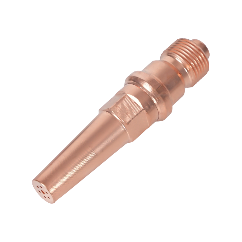
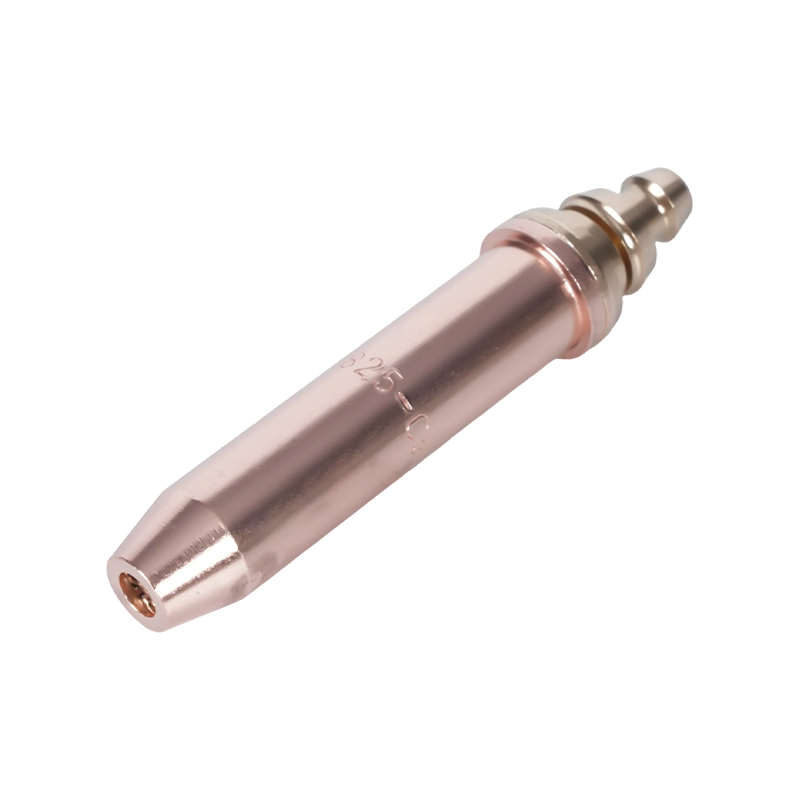
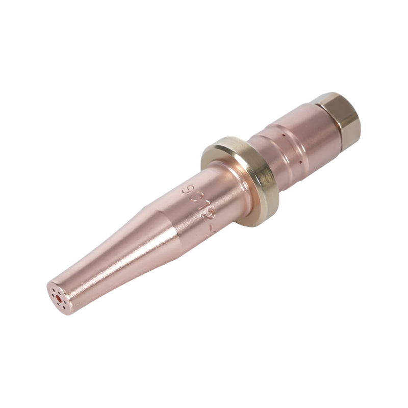
Oxy cutting tips — also referred to as oxy-fuel torch tips or nozzles — are the precision components at the business end of an oxygen-fuel cutting torch. They control the delivery of both the preheat flame and the high-pressure cutting oxygen stream, and their selection directly determines cut quality, cutting speed, gas consumption, and operator safety. Choosing the wrong tip for a given application is one of the most common causes of poor cut quality, excessive slag, warped metal, and premature equipment wear.
Oxy-fuel cutting remains the most widely used thermal cutting method globally, despite growing adoption of plasma and laser processes for certain applications. The equipment is portable, cost-effective, and capable of cutting mild steel from approximately 3 mm (1/8 inch) up to 300 mm (12 inches) in thickness — a range that no plasma cutter in a standard price bracket can match. The entry cost for a complete oxy-fuel setup is modest, typically between $250 and $350 for high-end hand equipment, and no electrical connection is required, allowing work to be performed in locations where power is unavailable.
Tips are manufactured from solid copper (one-piece construction) or as a two-piece hybrid with a brass inner piece and copper outer sleeve. One-piece tips are standard for oxygen-acetylene setups, while two-piece tips are typically used with alternate fuel gases such as propane, natural gas, and propylene. Each fuel gas burns at different temperatures and with different flame characteristics, requiring tips specifically engineered for that gas to optimize oxygen and fuel delivery ratios.
The Four Key Factors for Selecting the Right Oxy Cutting Tip
Selecting the correct oxy cutting tip requires evaluating four primary variables. Getting any one of these wrong compromises either cut quality or safety:
1. Torch Compatibility and Seat Type
Before any other consideration, the tip must be compatible with the specific torch model being used. Tip seats — the sealing surface where the tip connects to the torch body — vary significantly between manufacturers and even between models from the same manufacturer. Using an incompatible tip creates a dangerous condition: flammable gas can leak at the joint, creating a fire and explosion hazard. Always identify the torch manufacturer and model number before purchasing replacement tips, and verify compatibility against the manufacturer's tip chart or equipment manual.
2. Metal Thickness
The center orifice of a cutting tip — the bore through which the high-pressure cutting oxygen exits — is sized specifically to deliver the correct oxygen volume and velocity for a defined thickness range. As plate thickness increases, the bore diameter must increase to maintain an adequate cutting oxygen stream over the greater distance from nozzle to cut face. Using an undersized tip on thick material results in incomplete penetration and a rough, draggy cut. Using an oversized tip on thin material wastes oxygen, increases kerf width, and causes excessive preheating that can warp the workpiece.
The table below provides a general reference for acetylene cutting tip selection by metal thickness:
| Metal Thickness | Tip Size (General) | Oxygen Pressure (psi) | Fuel Gas Pressure (psi) | Cutting Speed (ipm) |
|---|---|---|---|---|
| 1/8" – 3/16" (3–5 mm) | 00 | 20 | 10 | 26–31 |
| 1/4" – 3/8" (6–10 mm) | 0 | 30–35 | 10 | 20–22 |
| 1/2" – 5/8" (13–16 mm) | 1 | 35–40 | 10 | 17–19 |
| 3/4" – 1" (19–25 mm) | 2 | 36–41 | 10 | 14–16 |
| 1-1/2" – 2" (38–51 mm) | 3 | 42–47 | 10 | 10–12 |
| 2-1/2" – 4" (64–102 mm) | 4 | 38–75 | 10 | 6–10 |
3. Fuel Gas Type
Different fuel gases require different tip designs because their combustion characteristics — flame temperature, heat release rate, and oxygen-to-fuel ratio — vary significantly. Acetylene produces the hottest flame of any common fuel gas, burning at between 5,600°F and 5,800°F, and provides the shortest preheat times for cutting and gouging. However, it is the most expensive fuel option and must never be used at pressures exceeding 15 psi, as it becomes unstable above that threshold. Propane and natural gas burn at lower temperatures (approximately 4,250°F for propane) and require longer preheat times, but they are considerably more cost-effective for high-volume heating and large-area warming operations. Tips designed for alternate fuel gases have additional preheat orifices to compensate for the lower flame temperature.
4. Bore Type: Cylindrical vs. Divergent
The geometry of the cutting oxygen bore — the central channel through which high-pressure oxygen travels — has a major effect on cutting performance for thicker materials. Cylindrical bore tips are the standard for hand cutting and machine cutting of thinner materials (1/8 to 3/8 inch) and operate optimally at approximately 40 psi at the torch inlet. Divergent bore tips, which flare outward toward the exit, maintain a higher-quality supersonic oxygen stream over a greater distance from the nozzle — making them the preferred choice for plate thicker than 3/8 inch. Divergent bore tips operate at higher pressures, typically 75 to 100 psi, but deliver faster cutting speeds and lower oxygen consumption per foot of cut compared to cylindrical bore tips at equivalent thicknesses.

Oxy Cutting Tip Maintenance and Common Problems
A cutting tip in poor condition is one of the most common causes of frustrating cut quality issues, even when all other parameters are correctly set. Regular inspection and cleaning of tips is essential for consistent performance.
Tip cleaning should be performed with the appropriate tip cleaner — a set of sized wire files matched to the orifice diameters. One-piece tips require a different cleaner than two-piece tips. The cleaning process involves gently running the appropriately sized file through each orifice to remove carbon deposits and spatter without enlarging the bore. Over-cleaning or using a file that is too large damages the orifice geometry, permanently degrading the tip's performance.
Common cut quality problems and their likely tip-related causes include the following. A rounded top edge on the cut is caused by excessive preheat — typically from an oversized tip or excessive fuel gas pressure. Drag lines that angle backward on the cut face indicate insufficient cutting oxygen pressure or a tip that is too small for the material thickness. A rough, uneven cut face with excessive slag adhesion points to a dirty or damaged tip orifice, incorrect travel speed, or contaminated oxygen supply. When these symptoms appear, inspect and clean the tip before adjusting gas pressures, as pressure adjustments cannot compensate for physical tip damage.
Stick Welding vs MIG: Understanding the Core Difference
Stick welding — formally known as Shielded Metal Arc Welding (SMAW) — and MIG welding (Metal Inert Gas welding, also called Gas Metal Arc Welding or GMAW) are the two most widely used arc welding processes worldwide. Both create a weld by generating an electric arc that melts a consumable electrode and the base metal to form a fused joint. But the way each process achieves this, and the conditions under which each excels, differ substantially.
In stick welding, a coated electrode — the "stick" — is clamped in an electrode holder and connected to a power source. As the arc burns, the flux coating on the electrode burns off to create a shielding gas that protects the molten weld pool from atmospheric contamination, simultaneously forming a slag layer over the cooling weld. In MIG welding, a solid wire electrode is fed automatically and continuously from a spool through a welding gun, while a separate tank of shielding gas — typically argon, CO₂, or an argon-CO₂ blend — is delivered through the gun nozzle to protect the weld pool. No flux coating is used, and no slag is produced.
The fundamental practical difference is this: stick welding is more portable, more tolerant of difficult surfaces and outdoor conditions, and lower in initial cost; MIG welding is faster, cleaner, and produces higher-quality welds in controlled environments. Neither process is universally superior — the right choice depends entirely on the application.
Stick Welding vs MIG: A Head-to-Head Comparison
| Category | Stick Welding (SMAW) | MIG Welding (GMAW) |
|---|---|---|
| Equipment Cost | Lower — simple setup, fewer components | Higher — wire feeder, gas tank, regulator required |
| Learning Curve | Easy to start, harder to master (arc length management) | Easiest arc process to learn; consistent wire feed helps beginners |
| Weld Speed | Slower — electrode must be replaced frequently | Faster — continuous wire feed, minimal downtime |
| Weld Cleanliness | Slag and spatter require post-weld chipping and grinding | Minimal slag; little to no post-weld cleanup needed |
| Outdoor Use | Excellent — self-shielding, unaffected by wind | Poor outdoors — wind disrupts shielding gas coverage |
| Surface Prep Required | Minimal — can weld over rust, paint, and mill scale | High — clean, bare metal required for quality results |
| Metal Thickness Range | Best on 1/8" and thicker; not suitable for thin sheet | Works on material as thin as 26-gauge up to thick plate |
| Portability | Highly portable — compact, no gas tank required | Less portable — gas cylinder and wire feeder add bulk |
| Best Applications | Structural steel, field repair, pipeline, heavy equipment | Automotive, fabrication shops, production environments |
Where Each Process Wins: Real-World Application Scenarios
Stick Welding: The Choice for Outdoor, Heavy, and Maintenance Work
Stick welding's self-shielding electrode means wind and drafts do not compromise weld quality — a decisive advantage on construction sites, outdoor pipelines, and agricultural repair work. The process handles rusty, painted, or mill-scaled surfaces far better than MIG, significantly reducing the time spent on surface preparation before welding begins. For structural steel work, heavy equipment repair, and pipeline welding, stick welding remains the professional standard in many industries. The deep arc penetration achievable with stick welding makes it particularly effective on thicker sections of steel and cast iron. Equipment portability is another major advantage: a stick welder can be carried to a remote work location without the need for a separate gas cylinder, making it the only practical choice for truly remote field repairs.
MIG Welding: The Choice for Speed, Cleanliness, and Thin Materials
In a controlled shop or production environment, MIG welding is almost always the more productive choice. The continuous wire feed eliminates the need to stop and change electrodes every few inches, dramatically increasing the time spent actually laying weld bead versus the downtime required in stick welding. MIG produces welds with minimal spatter and no slag, meaning finished parts require little to no grinding or cleaning before moving to the next production stage. For automotive fabrication, sheet metal work, and furniture manufacturing — applications where weld appearance and thin-material capability matter — MIG is consistently the preferred method. It is also widely regarded as the easiest arc welding process for beginners to pick up, since the automatic wire feed maintains a more consistent arc than the manually controlled electrode length required in stick welding.
When to Use Both
Professional welders and fabrication shops often maintain both processes. A common workflow involves using MIG for high-volume production runs of standard components in the shop, and switching to stick for field repairs, structural work on existing structures, or any job where shielding gas delivery is impractical. The most efficient approach to welding procurement and training is to treat stick and MIG as complementary tools rather than competing alternatives — each covers the limitations of the other, and together they address virtually the full spectrum of metal joining requirements.
Cost Considerations: Initial Investment vs. Long-Term Efficiency
Stick welding consistently wins on upfront cost. A basic stick welder suitable for serious work is available for significantly less than an equivalent MIG setup, which requires not only the welder itself but also a wire feeder mechanism, a shielding gas cylinder, a regulator, and a supply of wire spools. For occasional hobbyist use, small repair jobs, or budget-constrained operations, stick welding's lower barrier to entry is a genuine advantage.
The cost picture shifts for high-volume production environments. MIG welding's faster travel speeds, lower labor time per weld, and minimal post-weld cleanup costs can offset the higher initial equipment investment relatively quickly. The continuous wire feed also means that a MIG operator spends more time welding and less time repositioning, changing electrodes, and cleaning slag — which translates directly to higher productivity per hour. For industrial buyers and welding contractors taking on large fabrication contracts, the long-term cost efficiency of MIG welding frequently justifies the higher upfront capital requirement.
Consumable costs follow a similar pattern. Stick electrodes are inexpensive individually but are consumed at a rate that includes the non-weld time spent changing them. MIG wire and shielding gas represent a higher recurring cost per unit, but the per-inch-of-weld cost in a high-production environment is often competitive when labor efficiency is factored in. The decision between stick and MIG should always account for total cost of ownership — equipment, consumables, labor, and cleanup time — rather than purchase price alone.